Auto Design
Introduction
SmartDesign™ is an EasyPower feature that enables you to Auto Design: automatically size cables, circuit breakers, fuses and transformers based on the load the equipment is designed to carry. You can create a list of types and sizes of equipment to be used in Auto Design in the device library. For fuses and circuit breakers, you can create a list of desired manufacturers, types, styles and sizes. The standard library comes with a set of generic equipment to be used in Auto Design. This is adequate for typical designs.
You can select items in the EasyPower one-line and select the Auto Design command to size these items. The calculations for sizing of items are in accordance with NEC and typical design practice. Auto Design applies the new design on the one-line and creates a report.
Various options are available to provide you flexibility in the design process. While sizing circuit breakers, you can also select breakers that selectively coordinate with each other for high short circuit currents.
Items that Can Be Sized
- Bus Equipment: Low voltage distribution equipment such as switchgear, switchboard, panelboard, MCC, and panels.
- Cables: Low voltage cables.
- Protective devices: Low voltage fuses or circuit breakers.
- Transformers: Medium-to-low voltage or low-to-low voltage transformers.
Types of Circuits
When sizing equipment, the program differentiates the type of circuit and sizes accordingly. The following types of circuits are recognized.
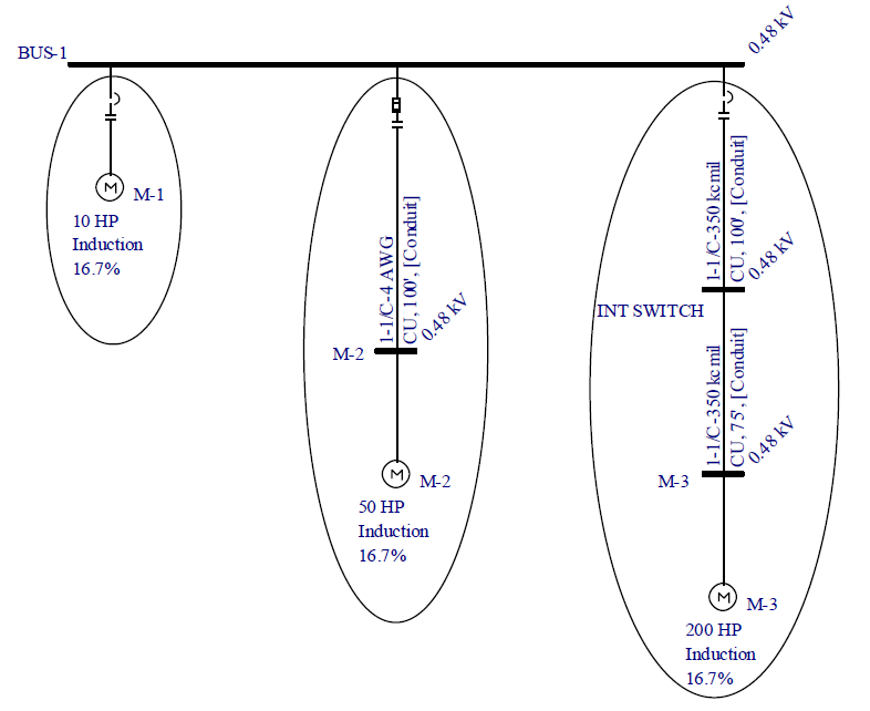
Motor Circuit: This consists of a motor, a cable feeding the motor and a protective device at the upstream end of the cable. See the picture below for examples. Each motor circuit is outlined with an oval. Circuits defined inside Panel or MCC data with a motor as the load type are motor circuits.

Figure 1: Examples of Motor Circuits
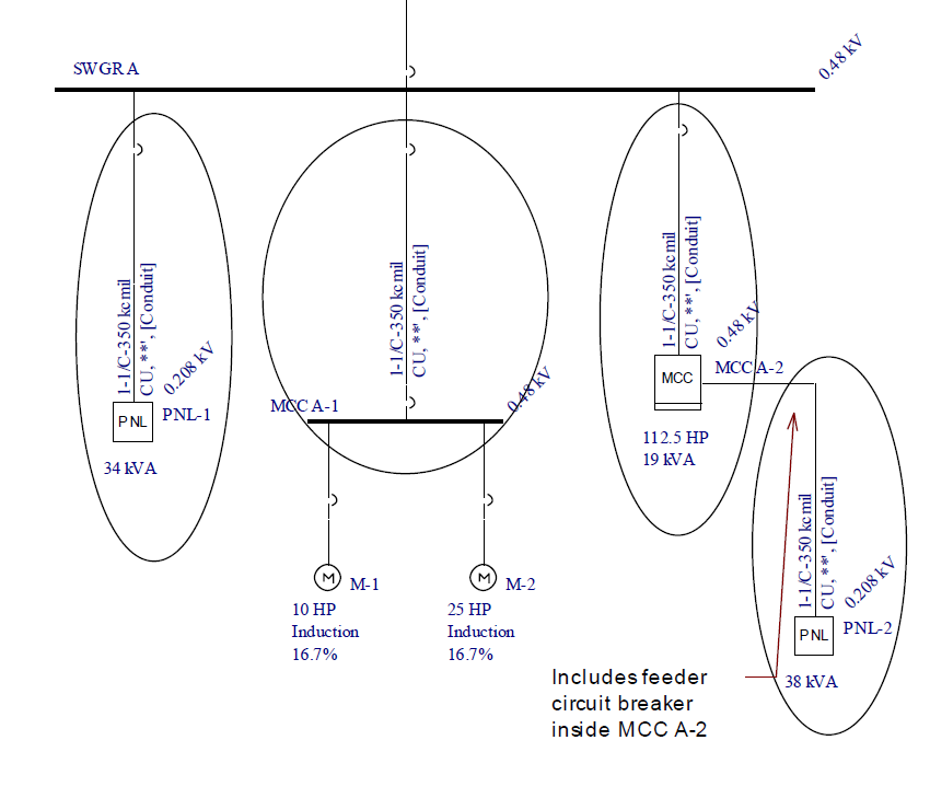
Feeder Circuit: A feeder circuit is a path between a distribution point (or bus item) and a load or between two distribution points (or bus items), and includes protective devices, cables and downstream bus items. See the picture below for examples. Each feeder circuit is outlined with an oval. Circuits defined inside Panel or MCC data with the load type Load (non-motor), are feeder circuits.

Figure 2: Examples of feeder circuits
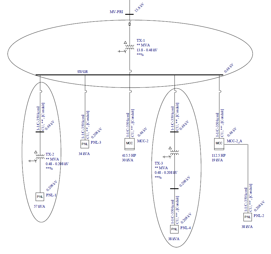
Transformer Circuit: A transformer circuit is similar to a feeder circuit, but includes a transformer. A transformer circuit begins at a primary protective device and ends a distribution bus on the secondary side. See the picture below for examples. Each transformer circuit is outlined with an oval.

Figure 3: Examples of Transformer Circuits
More Information
| Performing Auto Design | Design Library |
| Auto Design Options | Series Coordination of Breakers |

|